
Showcase
Livox Open Source Sharing: About LiDAR Distortion Removal
2021-12-20And when the LiDAR or vehicle is in motion, the self-motion distortion
I. What is LiDAR self-motion distortion?
LiDAR measures the distance and direction of surrounding objects by emitting laser beams and measuring relative location of a vehicle to an obstacle. When there are enough laser beams, these laser points will form a point cloud to plot the 3D information. This is what we often call point cloud data.
For most LiDARs, although the laser is transmitted and received quickly, each point that makes up the point cloud is not generated at the same moment. Generally, we output the data accumulated within 100ms (corresponding to a typical value of 10Hz) as one frame of the point cloud. If the absolute location of the LiDAR body or the body where LiDAR is mounted changes during this 100ms, the coordinate system of each point in this frame point cloud will be different. Intuitively, this frame of point cloud data will be "distorted" and will not truly correspond to the detected environmental information. It is like the case of taking a photo, if your hand shakes, the photo will be blurred. This is the self-motion distortion of LiDAR.
II. Essence of self-motion distortion and its calibration
Let's take a look at what self-motion distortion is.
The pattern of the self-motion distortion of LiDAR point cloud is related to its scanning method. For example, each frame of traditional 360-degree mechanical LiDAR is scanned from the points around the center of the LiDAR (100ms). When the LiDAR body or the host vehicle is stationary, the scanning start and end points will have a better matching (the coordinate origin always remains the same). And when the LiDAR or vehicle is in motion, the self-motion distortion will occur and the data for one round will be distorted, causing the surrounding points are longer matched (different points have different coordinate origins).
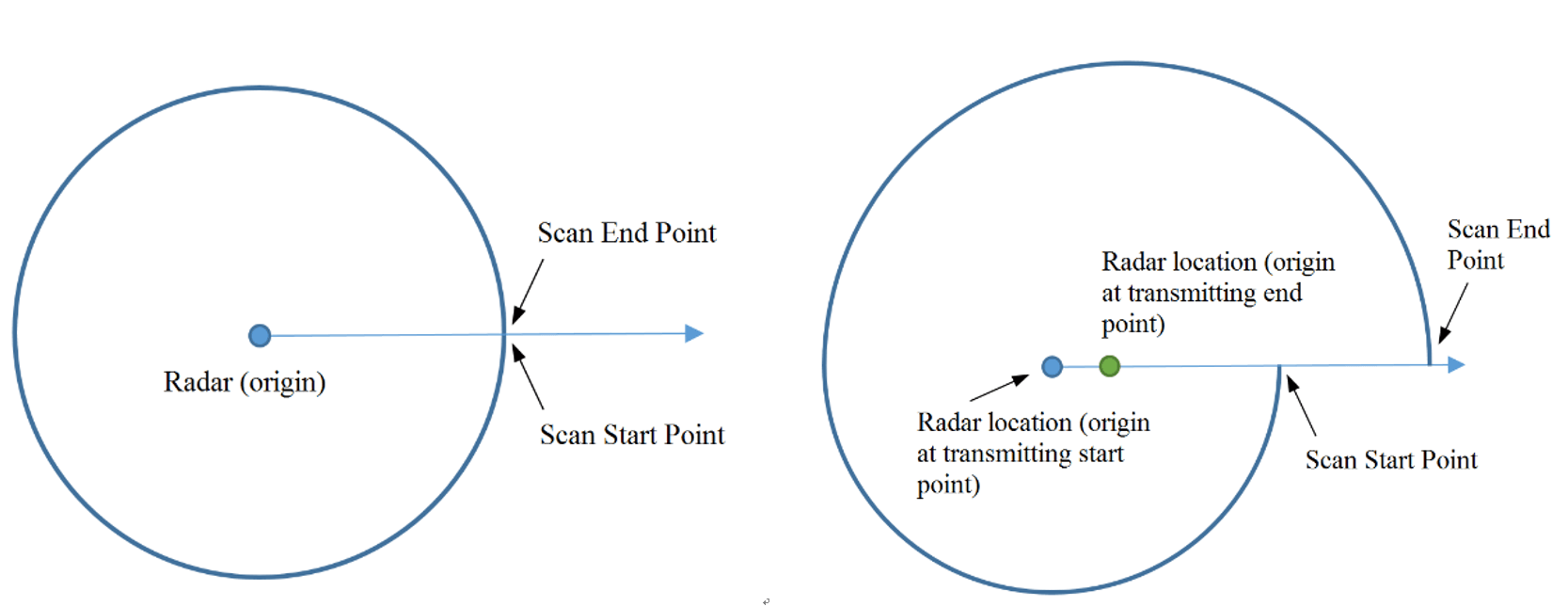
Figure 1. 360-degree mechanical LiDAR self-motion distortion schematic
Let's further analyze the essence of this phenomenon.
To put it simply, the self-motion distortion in the LiDAR point cloud is essentially the result of a different coordinate system for each point in a frame.
In the figure below, the left figure p1~p3 indicates the three location points scanned by LiDAR consecutively, which are co-linear in the real world. However, due to the "violent" motion of the LiDAR in one frame, the LiDAR scanned three points in three different attitudes, as shown in the middle figure. Therefore, in the final point cloud obtained (the rightmost figure), these three points are actually in different coordinate systems and no longer appear to be co-linear.

Figure 2. Point cloud coordinate system changes
Figure 3 gives an example of actual application.
Self-motion distortion happened when a vehicle is equipped with Livox LiDAR and makes a U-turn: Both the wall and the vehicle in the distance produced delamination due to the rapid rotation of the vehicle.
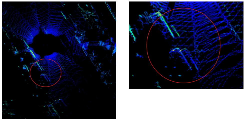
Figure 3. Point clouds of parked vehicles on the roadside are delaminated due to vehicle motion
So, how to amend the self-motion distortion? Apparently, if we drive the car slowly enough ...
Of course not, we need to convert the coordinate system of all points in one frame to the same coordinate system where the first point p1 is located as shown in Figure 1, which is essentially a compensation for the motion of the LiDAR.
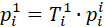
We use p1i to indicate the coordinate of pi in the LiDAR Coordinate System 1, and T ji to indicate the location change of coordinate from i to j. In a frame point cloud, the changes of each point to the first point coordinate system are T12, T13, T14 … the corresponding point can be easily transferred to the coordination of the first point:
It looks very simple in principle (and very simple in practice). As long as you knowT1i at each point, so how can we know it?
In practical applications, generally, first try to measure the motion information of the LiDAR, such as the location change T of a frame point cloud (100 ms interval). The T1i of a point is then obtained by linear interpolation based on the time difference Δt between a point and the initial or end point by the short-time uniformity assumption. The location change T can be acquired through the inertial navigation system (INS) or LiDAR Odometry (e.g., LIO ). If an inertial measurement unit (IMU, which can provide angular velocity and acceleration information) is used to calculate the location change, additional information on the initial velocity of the LiDAR or vehicle is required.
And how do you get the value of Δt? The Livox LiDAR output comes with a timestamp for each point. The point cloud can be read directly from the point cloud data package Custom Msg. Other type of LiDARs may need to get the timestamp for each point based on the information form SDK or through manual calculation.
Converting the coordinate of each point in each frame to the same coordinate system according to the above formula is the process of distortion removal.
Figure 4 below shows the point cloud comparison before and after distortion removal.
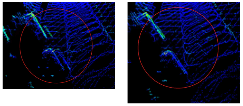
Figure 4 shows the results after point cloud calibration
III. Use of self-motion distortion calibration tool and instructions
We have uploaded the above distortion removal process code to GitHub, if you are interested, please click here.
Code notes:
Rely on:
livox_ros_driver
PCL
ROS
Compilation: Use commands under workspace
catkin_make
Run:
source develop/setup.bash
roslaunch livox_distribution_pkg run.launch
Interface notes:
ImuProcess class is defined in data_process.h. The member function UndistortPcl of this class is de-distortion function, the function parameter Sophus::SE3d Tbe is the location between current frame point cloud frame head and frame tail, if the location can be provided directly, then the function can be called for distortion removal. If only IMU data is available, Process - the member function of ImuProcess is called for distortion removal.
Special notes:
The calibration of offset distortion requires the user to manually calculate the offset change under the corresponding time difference according to their respective offset information sources (GPS position coordinate, speed, etc.) and input it as the function UndistortPcl in the code.
Use:
Input:
This tool is developed from ros, so the input information has two topics, the point cloud topic is /livox/lidar, customMsg format, and the IMU information topic is /livox/imu
Output:
The output is the calibrated point cloud /livox_unidistort