
Showcase
a Robust LiDAR-inertial Odometer with LIO-Livox Open-source Algorithm
2021-8-4In this article, we offer a solution by using a single Livox Horizon unit (with a built-in IMU) to create a robust LiDAR-inertial odometer that operates robustly in various extreme scenarios and delivers high-precision localization and mapping results: Cross the urban congestion, cross the highway, realize the robust positioning in the dark tunnel.
With its unique solid-state rotating-mirror scanning technology and ultra-competitive cost-performance ratio, Livox has completely changed the industry perception that high-performance LiDAR sensors must come with a hefty price tag. To help users implement this new LiDAR technology quickly, Livox has introduced a number of sensor algorithms adapted to unleash Livox LiDAR’s superb performance.
Meanwhile, we noticed that certain users have been experiencing some challenges when applying the device in high-speed SLAM scenarios. In this article, we offer a solution by using a single Livox Horizon unit (with a built-in IMU) to create a robust LiDAR-inertial odometer that operates robustly in various extreme scenarios and delivers high-precision localization and mapping results.

Figure 1: The system travelling through a 4-km tunnel at 80km/h

Figure 2: A forward-facing Livox Horizon LiDAR mounted on the roof of a demo vehicle
Video 1: SLAM when the demo vehicle travels through the tunnel (with comparison from camera’s point of view)
The following is a description of the open-source system.
The system consists of two modules: ScanRegistration and PoseEstimation.
ScanRegistration is responsible for filtering dynamic objects from the raw point cloud and extracting features for pose estimation.
In the PoseEstimation module, the main thread performs IMU initialization and status estimation, while the other thread generates and manages the feature map.
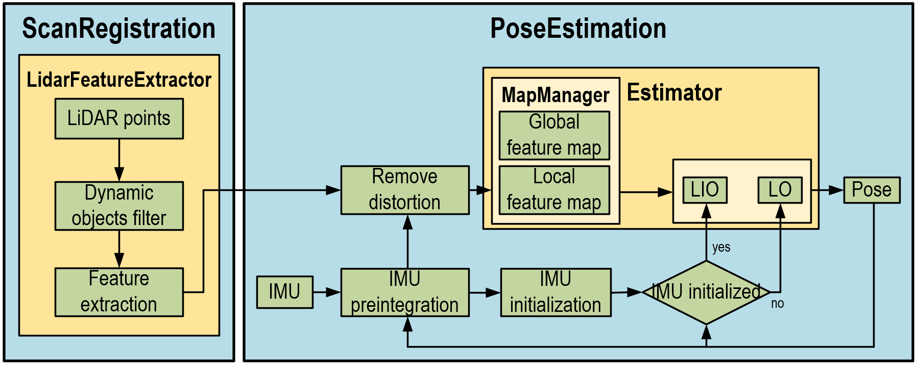
Figure 3: System workflow
01.
Dynamic objects filtering_ScanRegistration
Multiple dynamic objects can appear in an urban scenario, such as cars and pedestrians, which may impact the robustness and precision of LiDAR or camera’s localization feature. Therefore, a point cloud segmentation method is required for filtering dynamic objects fastly.
We use the Euclidean clustering method to group the raw point cloud into ground points (blue), background points (green), and foreground points (yellow), as shown below. The foreground points (yellow) are treated as dynamic objects and therefore filtered out during the feature extraction process. After the filtering, the system will be able to maintain high robustness in dynamic scenarios, and localize and generate maps with great accuracy even when LiDAR’s field of view is largely blocked by a dynamic object.

Figure 4: Illustration of point cloud segmentation
Blue points: ground; green points: background; yellow points: dynamic objects in the foreground.
02.
Feature extraction_ScanRegistration
The feature extraction method needed here is one that can spread the features as wide and evenly as possible across the six degrees of freedom, in order to create more constraints to stabilize the system. If this is achieved, we can prevent system degradation for certain degrees of freedom even when only a few features are extracted from an open-space scenario.
Besides, irregular features can also act as useful constraints in scenarios with fewer features. We extract these irregular features as a separate category for use in point cloud matching and map maintenance.

Figure 5: Feature extraction workflow
As shown below, features can be categorized into the following three types based on their local geometric properties: corner features, surface features, and irregular features. First, extract the points with large curvature and isolated points on each scan line as corner features. Then use the PCA method to distinguish between surface and irregular features. Different thresholds should be used for the extraction of features at different distances, enabling the features to spread as evenly as possible across the space.

Figure 6: Illustration of features
Green points are corner features, pink points are surface features, and blue points are irregular features.
03.
IMU initialization_PoseEstimation
In the PoseEstimation module, the system may use the IMU preintegration or uniform motion model, depending on the fusion mode, to remove self-motion distortions from the point cloud and perform IMU initialization. If the initialization is successful, the system will switch from LO mode to LIO mode; otherwise it will continue operating in the LO mode and attempt to perform initialization.
In the LO mode, we use the frame-to-model point cloud registration method to estimate the sensor’s pose. Borrowing from the principles of ORB-SLAM3 algorithms, we adapt Maximum A Posteriori estimation to IMU initialization, to simultaneously estimate IMU’s bias, velocity and gravitational orientation. This takes into consideration the uncertainty of the sensor itself while achieving an optimal solution based on the Maximum A Posteriori estimation.
When the initialization is completed, the system will execute a tightly-coupled sensor fusion module based on sliding windows to optimize IMU’s pose, velocity and bias in the window.
Meanwhile, the system uses an additional thread to generate and maintain a global map in parallel.
04.
Robustness testing_Entire system
We have conducted numerous tests in various urban scenarios where the system exhibited great robustness. It was able to operate normally in a range of extreme scenarios.
For instance, the tunnel environment described above is prone to laser degradation for SLAM due to the plain nature of the scenario. Our system is able to travel through a 4-km tunnel without experiencing degradation primarily because of extensive range and high measurement precision of Livox Horizon. With only a 81.7° forward-facing FOV, it can acquire a multitude of data from the scenario, such as those on randomly placed traffic signs in the tunnel and grooves on the walls. The tight coupling between these data and IMU act as constraints and safeguards for any direction prone to degradation.
Laser degradation tend to happen more easily on intercity highways due to their open space nature and the lack of structural objects - which generates fewer usable data - as well as the higher travelling speed of cars on highways. However, the feature extraction method we have opted for ensures that various data including those on lampposts, road signage and vegetation can be fully utilized. The relevant features provide constraints for the forward-moving direction, thus enabling the system to operate with exceptional robustness even on intercity highways.
As shown in the video below, we travelled more than 10km of city roads, driving past dense high-rises, through residential areas, under overpasses, over highways, and through tunnels and forest areas. We encountered several traffic jams where we were continuously surrounded by moving vehicles. The system performed well and showed a great robustness, without any failure in various extreme scenarios, and demonstrated a high level of precision. The point-cloud map functioned well after being registered on Google Maps.
Video 2: SLAM when the demo vehicle runs on an intercity highway (with comparison from camera’s point of view)
A large amount of dynamic objects can appear in an urban scenario. This is especially true during traffic jams, where many moving vehicles can block LiDAR’s vision while creating bias in pose estimation. Our system filters out dynamic objects and greatly minimizes their impact, enabling the device to well respond to any ultra-dynamic urban scenario.
Video 3: SLAM when the demo vehicle travels in an urban scenario (with comparison from camera’s point of view)
05.
Conclusion
With robustness as our goal, we have developed a vehicle-mounted LiDAR-inertial odometer suitable for outdoor use. The superb performance of Livox Horizon makes it an optimal hardware platform for deploying our algorithms and achieving superior robustness in various extreme scenarios. Despite·using·only·a·single·Livox·Horizon·unit·built-in·with·a·six-axis·IMU,·the·system·was·able·to·deliver·remarkable·results. To help users better understand and use our LiDAR sensor, we have shared on GitHub the source code for this system along with detailed user instructions.
Github Source: https://github.com/Livox-SDK/LIO-Livox