
Showcase
Livox Showcase - UAV 3D Mapping
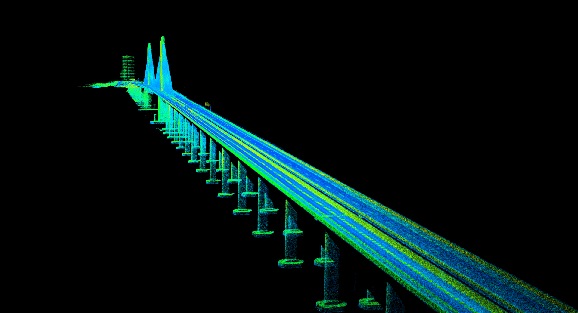
2019/4/24To demonstrate the great potential of Livox LiDARs in 3D mapping, this showcase how they can be integrated into a drone to accomplish mapping tasks. As a test, the 3km-long Huizhou Bay Bridge, located in Huizhou, Guangdong, China was mapped.
Livox is dedicated to providing low-cost high-performance LiDAR sensors to a large scope of industries including automotive, robotics, surveying, and more. With the release of MID-40, a $599 high-performance 3D LiDAR ready for delivery, Livox aims to bring extremely affordable LiDAR technologies to robotics navigation and mapping. Key specs of the MID-40 can be found at https://www.livoxtech.com/mid-40-and-mid-100/specs. Selected specs are also shown in Table 1.
Table 1. Selected basic specifications of MID-40
|
| |
|---|---|
| Laser Wavelength | 905 nm |
| Laser Safety | Class 1 (IEC60825-1) |
| Detection Range (@ 100 klx Background) | 90 m @ 10% Reflectivity 130 m @ 20% Reflectivity 260 m @ 80% Reflectivity |
| Distance Precision (1σ @ 20 m) | 2 cm |
| Angular Accuracy | < 0.1° |
| FOV | 38.4° Circular |
| Data Rate | 100k points/s |
| Typical Power | 10 W |
| Weight | Approx. 710 g |
| Dimension | 88×69×76 mm |
| Operating Temperature | -20˚C to 65˚C (-4˚F to 149˚F) |
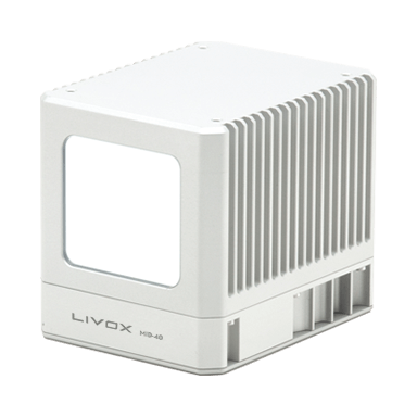
Figure 1. The Huizhou Bay Bridge and its mapped point cloud, overlapped with each other

(a)
(b)
Start with integrating one Livox MID-40 unit with a GNSS-INS Sensor from Inertial Sense which provides high-grade attitude measurements. A RTK unit is also used with the INS sensor to provide centimeter-level positioning services. The Livox MID-40 and INS sensor are securely connected to avoid any relative movement. An onboard Raspberry Pi microcomputer is usedo process the MID-40 data and the INS measurements in real time. Livox LiDARs support external INS/RTK with both hardware-level time synchronization and software-level sensor data fusion. Detailed instructions on integrating Livox LiDARs with INS/RTK and data processing can be found at https://github.com/Livox-SDK/LivoxIntegration.
Figure 2. Main components used in this setup
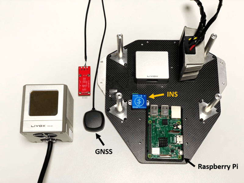
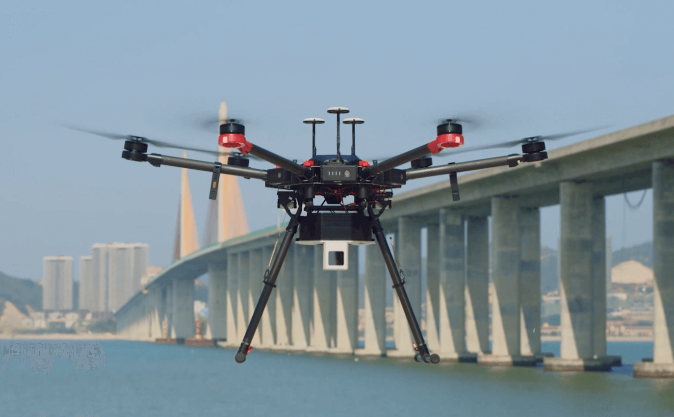
Figure 3. MID-40 on M600 drone
INS and GNSS are necessary to compensate for LiDAR movement (both rotation and translation) during drone flight. Although the drone itself is equipped with an IMU inside its flight controller, it is usually insulated from the drone’s airframe (hence the LiDAR sensor) by some dampers to absorb vibrations due to the propeller rotation as well as the various drone modes. Vibration insulation for IMU is useful and sometimes necessary for drone control. However, for applications such as sensor fusion and mapping, we do need to measure all possible LiDAR movements, including vibration.
The drone used is the DJI M600 since it is what we had on hand. With the size and weight of MID-40, a smaller drone such as M200, M210 (RTK) or more recent M220 are also suitable. For mechanical integration, benefiting from the various mounting options enabled by Livox MID-40 (see the Livox MID-40 Quick Start Guide), mounting a Livox MID-40 to a DJI M600 is quite straightforward, with simple mechanical parts. For electronic hardware integration, a DC-DC voltage regulator is used to step the drone battery voltage (22V) down to the MID-40 input voltage (10V to 16V) and the Raspberry Pi input voltage (5V).
During the mapping, the distance between the drone and the bridge was about 50m, which is limited by the INS sensor being used here. Longer distance could lower the point accuracy as the attitude measurement error caused by the INS sensor is amplified by this distance. With a higher-grade INS (e.g. APX-20 or NovAtel’s SPAN), the distance could be longer and the data collection, in turn, can become more efficient. For the Huizhou Bay Bridge, the data collection process takes half a day with a single MID-40, with a post-process that takes less than half an hour.
All the LiDAR data and INS measurements – including RTK measurements – are saved to a microSD card on Raspberry Pi. With the saved data, post-processing is as simple as applying the rotation and translation measured by INS sensor to LiDAR data, so all point data are projected to an Earth frame to build a global map.
Figure 4. The mapped bridge serial, viewed from different angles
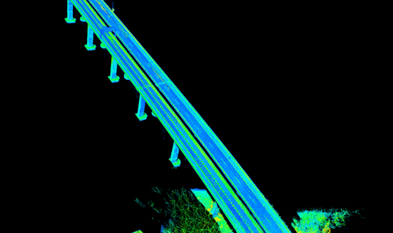
(a)
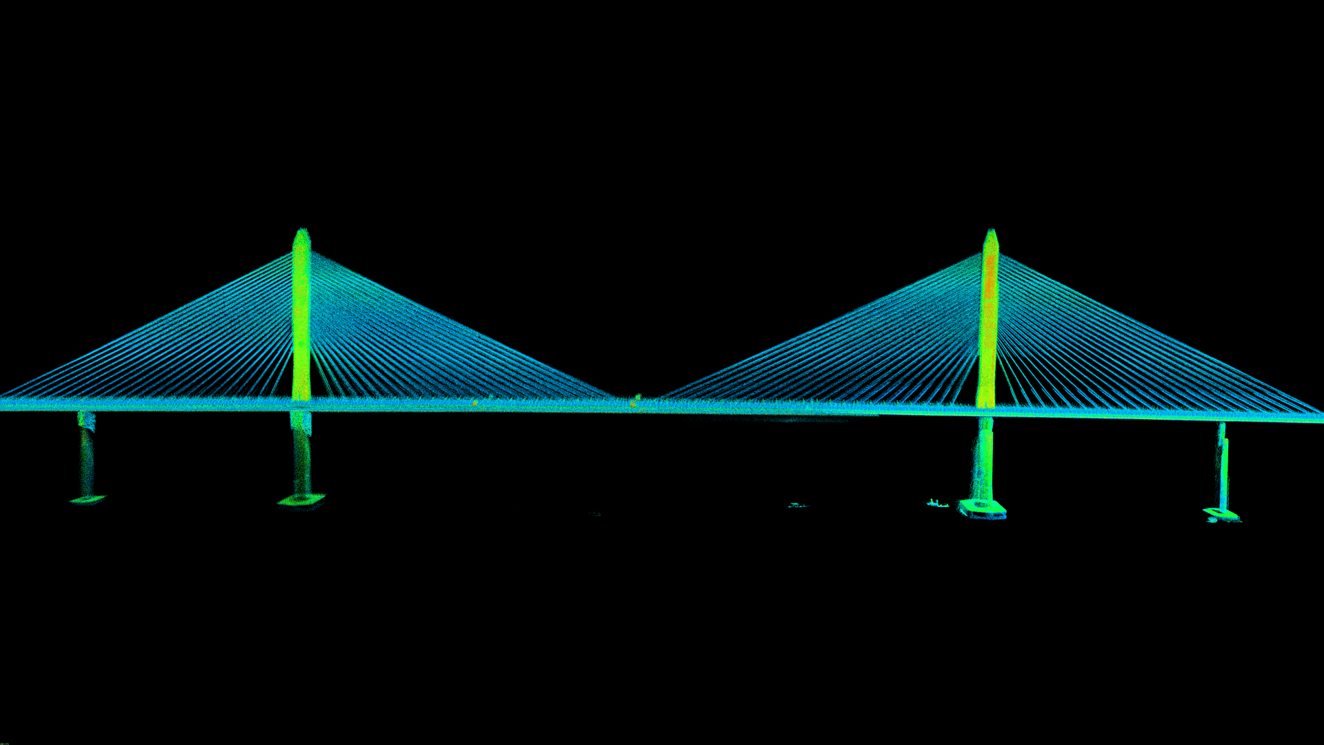
(b)
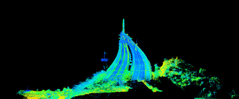
(c)
As shown in Figure 4, with a single MID-40, the entire bridge was mapped down to its finest details. The stay cables are well separated from one another and the marks on the bridge surfaces are clearly seen. With Livox LiDARs, aerial mapping has become more efficient and affordable than ever. The case shown here hasn’t been polished to the best effect yet – there is still a large room for increasing mapping accuracy, which can be achieved by higher-grade INS, more sophisticated post-processing algorithms (e.g. SLAM), or other solutions provided by developers. But from here, it is not hard to imagine Livox LiDARs’ unlimited potential.
You might find the open source of a similar project at: https://github.com/Livox-SDK/livox_high_precision_mapping